Table of Contents
Start Page » Game Development with the Drag[en]gine » Camera Tone Mapping
IGDE
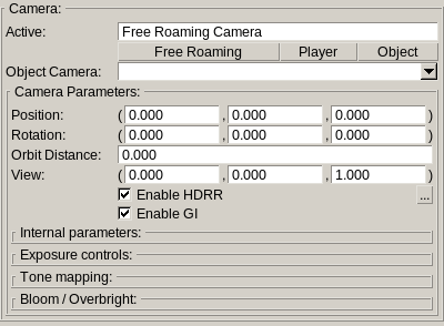
 In the IGDE you can modify the camera properties in editors. These camera settings apply only to the editor they are changed in and allows to test different settings without changing the camera settings used in the game later on. The camera panel is split into different sections controlling different aspect of the camera. Next to the “Enable HDRR” button is the camera menu (button with text “…”). This menu has the following entries
Set Default Indoor
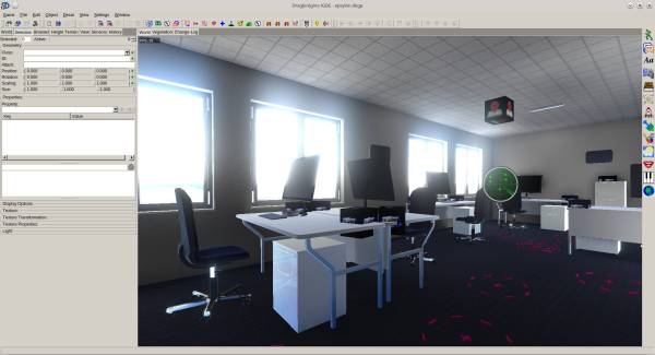
Resets camera parameters to default parameters suitable for indoor scenes. This sets the lower and upper camera intensities to 1. No dynamic exposure control is used. Typically indoor scenes use lights with intensities between 0.5 and 2 (0.5 for cozy light, 1 for living rooms and 2 for office/public spaces that are well lit).
Set Default Day
Resets camera parameters to default parameters suitable for outdoor scenes at day. This sets the lower and upper camera intensities to 20. No dynamic exposure control is used. Typically outdoor daylight scenes use sky lights with intensities between 4 and 20 (4 for heavily overcast, 10 for overcast and 20 for clear sky).
Set Default Night
Resets camera parameters to default parameters suitable for outdoor scenes at night. This sets the lower and upper camera intensities to 0.1. No dynamic exposure control is used. Typically outdoor night time scenes use sky lights with intensities between 0.01 and 0.1 (0.01 for heavily overcast, 0.05 for overcast and 0.1 for clear sky).
Set Default Dynamic
Resets camera parameters to default parameters suitable for variable lighting condition scenes. This sets the lower camera intensity to 1 and the upper camera intensity to 20. Exposure is automatically adjusted to match the lighting condition. Adaption time is set to 0.1 which is suitable for editing. For games this is usually set to 10 to 30 seconds depending the needs.
Load...
Loads camera settings from *.decamera files, which are XML files.
Save...
Saves camera settings to *.decamera files, which are XML files.
When using DragonScript Script Module these settings can be loaded using LoadCamera class. A typical code looks like this:
pin Dragengine.CameraDirectors

class MyClass
   var CameraDirector myCameraDirector
   var CameraDirector cameraSettings1

   func void MyFunction()
      // Load camera settings from file and apply them to the camera director.
      // This overwrites all camera related parameters. This does not overwrite
      // CameraDirector specific settings like position or orientation
      BaseGameApp.getApp().getLoaders().getCamera().loadFromFile("/content/cameras/default.decamera", myCameraDirector)

      // Optionally you can load the settings into a temporary camera director
      // stored in your game. This can be used to load different camera settings
      // and switching between them during the game.

      // This loads the camera setting into a separate camera director
      cameraSettings1 = BaseGameApp.getApp().getLoaders().getCamera().loadFromFile("/content/cameras/settings1.decamera")

      // Now you can apply the settings from cameraSettings1 to myCameraDirector.
      // As with loading this replaces only camera related parameters.
      myCameraDirector.copyParameters(cameraSettings1)
   end
end
Camera Parameters
This panel shows the camera parameters. This includes editor only parameters (like position and orientation) that are not saved to camera files and those that are (enable hdrr and enable gi).
Internal Parameters
 Contains parameters related to the internal functioning of a camera. Often called intrinsic parameters this describes the lens of the camera and how the world is rendered.
Field of view
Defines the opening angle of the camera in degrees. This is the horizontal angular area captured by the camera. Typical values are:
- 39.6: Normal camera FOV
- 65.47: Wide camera FOV
- 83.97: Ultra wide camera FOV
- 22.62: Short tele camera FOV
- 10.29: Medium tele camera FOV
- 6.87: Long tele camera FOV
- 90: Typical first person FOV
- 75: Shorter first person FOV as often seen in first person shooters
Field of view ratio
Ratio between the vertical opening angle and the horizontal opening angle (ratio = vertical/horizontal). There is usually no need to change this since the game engine ensures the correct ratio to obtain a disctortion free image. You can though change this to produce distorted result. A typical use case for this is simulating nausea or drugged view of a player that shimmers or waves.
Image distance
The distance in meters to the far view plane of the camera. World geometry is not rendered beyond this distance. Setting this distance too large can cause slow rendering and other problems. It is best to keep this distance as short as possible. The default value is 200 meters. Typical settings for game vary between 100 and 1000 (100 for games with small worlds, 300 to 500 for first person shooter games up to 1000 for games requiring long view distances).
View distance
The distance in meters to the near view plane of the camera. World geometry is not rendered closer than this distance. This distance always has to be larger than 0. The default value is 0.01 . It is best to keep this distance as large as possible without geometry near the camera beginning to clip.
Exposure control
 If HDRR rendering is used by the game engine intensities cover ranges beyond 0 to 1. To get the intensities back into ranges suitable for LDR displays exposure control is used. The average scene intensity is measured and the exposure automatically adjusted to map the world intensites to a suitable range.
Lower intensity
Lower intensity the camera can automatically adjust the exposure to. If lower and upper intensity are the same automatic exposure control is disabled.
Higher intensity
Higher intensity the camera can automatically adjust the exposure to. If lower and upper intensity are the same automatic exposure control is disabled.
Exposure
Multiplier applied to the automatically adjusted exposure for fine control. The default value is 1 keeping the automatically chosen exposure unchanged.
Use values larger than 1 to brighten the image. This increases the contrast at the risk of colors washing out to white. This tends to produce harder looking (higher contrast) images. Adjusting the tone mapping white point can compensate for this.
Use values smaller than 1 to darken the image. This decreases the contrast and reduces the risk of colors washing out to white. This tends to produce softer (lower contrast) images. Adjusting the tone mapping white point can compensate for this.
Adaption time
Time in seconds required for automatically adjusted exposure to stabilize. Exposure is not immediately changed. Instead it is gradually adjusted to move towards the chosen exposure level. This simulates the exposure adjustment behavior of human eyes. The adaption time is not a strict value. It is more of an indication how long it roughly takes for the exposure to be fully adjusted. Typical values used are:
- 0.1: Pretty much immediately adjust exposure
- 1: Adjust exposure very fast
- 10: Adjust exposure faster
- 20: Adjust exposure slower
- 30: Adjust exposure slowly
Real human exposure changes are between 1-5 minutes depending on lighting conditions. For games this is usually too long. Hence the values are typically shorter.
Tone mapping
 Tone mapping is the process of remapping large intensities in the rendered image to the range from 0 to 1 to display on LDR displays. In contrary to human eyes displays use lower intensity ranges. Some monitors supported larger ranges (HDR monitors) but the problem stays the same just with better resolution along the supported intensity range.
In the course of game development and 3d rendering various tone mapping operators have been designed. Most of the time a kind of flimic curve is used. This is an S-shape curve this compresses high intensites and enhances dark intensities. The shape between these operators various but all stick more or less to the S-curve. The Drag[en]gine OpenGL module uses a filmic curve which modified to produce balanced images. This means no harsh contrast, no harsh black blow-up while still allowing for over-brighting effects to work out.
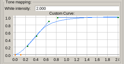
In general games build using the Drag[en]gine should not worry about the actual tone mapping used. Instead a general white intensity is used to adjust the wideness of the tone mapper. For the majority of situations this is enough. For those requiring fine control over the tone mapping curve a custom curve can be set.
White intensity
Defines the white intensity level. This is used for both the internal tone mapper and the optional custom tone mapper curve.
For the internal tone mapper the white intensity defines the intensity level after exposure control that should map to pure white. The default value is 2 which indicates intensities larger than 2 times as bright (after exposure control) wash out to white. The actual world intensity mapping to an intensity level of 1 after exposure control can be difficult to pin-point if automatic exposure is used. It is thus often required to manually tweak the value to find a good value for the scenes to cover. Values up to 4 for example reduce the contrast in the image but in favor of colors to not wash out to white that fast.
For custom tone mapping curve this the intensity level (after exposure control) that maps to the right end of the tone map curve. Usually this is the point in the curve where the X value matches the white intensity and Y value becomes 1.
Tone Map Curve
Custom tone mapping curve is used if the set curve has at least one curve point. Hence to disable custom tone mapping clear the curve.
Instead of providing an exhaustive list of tone mapping operators the Drag[en]gine allows to define a tone mapping curve instead. In the end all tone mapper operators are a function mapping an input value (HDRR) to an output value (LDR). Hence defining a curve is as good as adjusting parameters of a tone mapper algorithm you do not know. The curve is required to have the starting point X=0 mapping to Y=0 and an end point Y=1 at the right side. The end point should be located at X=white-intensity but it is not a dire requirement. Although it is possible to use any kind of shape tone mapping curves should be monotonically increasing which means each Y value to the right of the any X value has to be equal or larger.
When designing an own curve it is best to start out with a default bezier curve then adjust the left end to have a small incline section with a linear section before leading in a long and gently arching right side. The left side is typically called the “toe” of the curve. This defines how strong or gentle dark area are rendered. The right side is typically called the “shoulder” of the curve. This defines how high values are squashed. The shoulder is typically much wider than the rest of the curve typically covering 75% of the curve. Playing around with this can give you the results to you desire.
Bloom / Overbright
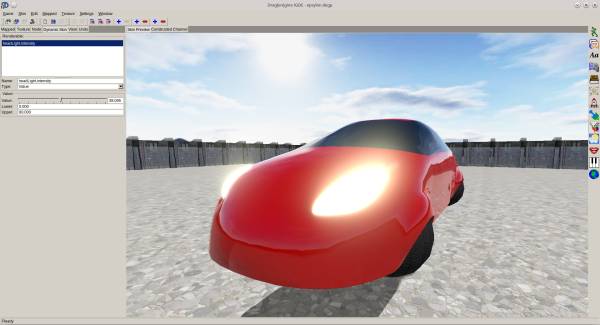
 After tone mapping there are usually some intensities left above the white intensity. To give the sense of very bright light sources these are often blurred to obtain an effect called “bloom” or “overbright”. In human eyes this happens due to the chemicals of rods and cones being so saturated they affect nearby rods and cones raising their trigger level. In camera lenses imperfections cause similar effects.
Blend
Switches the effect on and off. Allows to gradually blend between enabled and disabled.
Intensity
The intensity level (after exposure control) where over-brighting effect has to take effect. This is the ground threshold intensity. The intensity used for the over-bright effect is the intensity (after exposure control) minus the bloom intensity.
Strength
Multiplier applied to the intensity (after bloom intensity). This indicates how strength of the over-bright effect relative to the exceeding intensity. This value allows to fine tune the strength of the effect for different tone mapping parameters. The default value is 0.25 . If you scene has many strong lights reducing this value can help to avoid harsh blooming.
Size
Indicates the size of the blurring relative the the screen width. The default value is 0.25 which equals to a blur radius of 25% of the screen width.

