Table of Contents
Start Page » Game Development with the Drag[en]gine » LOD System
A good and fast game engine requires all kinds of LOD systems. Although graphic cards become faster and faster they still have huge troubles rendering large scenes with many polygon heavy objects. This problem is even intensified by the fact that with increasing distance the number of objects in the field of fiew grows exponentially if they are evenly spaced. Especially at the distance though the complex details of objects are barely visible. In this case a much lower polygon object is enough to obtain a visually pleasant render. While Graphic Modules could automatically create LOD versions of models if they want to it is better to have the artist provide LOD versions himself. Artists have additional knowledge about what is important on a model that automatic methods do not have.
Model Resources and LOD
LOD systems vary a lot from one game engine to the other and many of them are full of limitations and problems. The artist has to know the peculiarities of the LOD system used in a game engine to create models LODing properly. Small changes in parameters can quickly upset the LOD system. Some even do not allow specific tricks to aggressively LOD models. The Drag[en]gine on the other hand uses a very simple LOD system which imposes no restrictions at all to the artist.
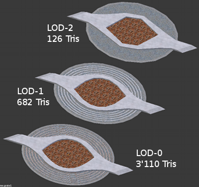
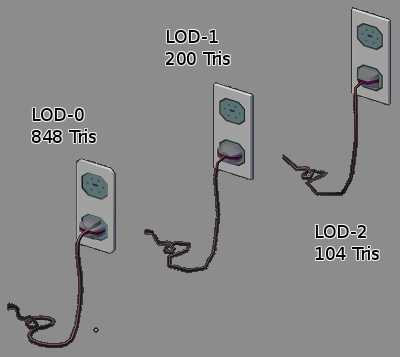
LOD versions of models are directly stored in the model itself and thus directly stored in the model files themselves. This has been chosen to keep files organized. LOD meshes and their base mesh are so closely linked separating them produces a lot of extra synchronization and management code that just doesn't justify splitting them apart. Storing the LOD meshes alongside the base mesh in the model allows all meshes to use the same bones and textures. Animatable objects can thus be lodded the exact same way as any other model. The number of LOD meshes in a model is not limited. You can use as many as you see fit to reduce the polygon count gradually to the utmost minimum. You are also not forced to just remove individual vertices only from the base mesh to the LOD mesh as some game engines require. The LOD meshes are totally free concerning the number and placement of vertices and faces connecting them. compared to each other. It is only important to keep the surface points close to each other since the proposed LOD metric works best in this case.
LOD meshes work perfectly together with dynamic textures and texture replacement techniques. Replacing textures is fully transparent towards LOD meshes and adding, removing or changing LOD meshes is fully transparent towards texture replacement techniques.
LOD Metric
The Drag[en]gine itself does not force a LOD metric to be used. The Graphic Modules are free to use whatever LOD metric they see fit to produce the best results from the model provided to them by the artist. The following LOD metric though has been implemented into the default OpenGL Graphic Module as it provides a very good result with good LODing possibilities. It is thus adviced for other Graphic Modules to adopt this LOD metric in one way or the other.
Most of the time LOD metrics in game engines are quite cheap and because of this rather inneficient. The most simple solution is to switch from one LOD level to the next after a constant distance from the viewer. While this metric is simple to implement the results can be quite suboptimal. The artist has to adjust the LOD mesh creation to the LOD distance of the game engine. This distance is not optimal for all models. LOD meshes have to be created at a distance where not as many triangles can be spared while still producing popping and jumping between LOD levels. A more advanced solution is to let the artists assign the LOD distance himself on a per model basis. If the field of view of the game changes or objects can be seen through remote cameras all these techniques break down quickly. Changes in the rendering can quickly force artists to redo LOD meshes which is a lot of extra work for poor results.
The LOD metric used in the OpenGL Graphic Module operates on the idea of the pixel error instead. What is interesting is not at what distance to switch the LOD mesh but what the error between the shapes of a LOD mesh compared to the base mesh is in screen pixels. Switching from the base mesh to a LOD mesh is perceived as popping if the diference between two shapes at their most extreme points is larger than one screen pixel. The best LOD metric thus switches only to a higher LOD mesh if the error measured in screen pixels is at most 1 pixel. The error is best measured on the plane touching the front side of the model as there the erorr is the largest. The OpenGL Graphic Module calculates for each LOD mesh in a model the maximum and average error in meters between surface points of the LOD mesh and the base mesh. Once calculated these errors can be simply projected onto the image plane resulting int he maximum and average pixel error for this model. The LOD mesh with the highest pixel error still less than the user defined threshold is chosen. In the running game it is next to impossible to notice when objects switch LOD meshes while still using the highest possible LOD mesh. The interesting property is that using the screen pixel error this LOD metric works transparently for all rendering situations. It works with rendering from cameras no matter if large or small, from remote-cameras, from mirrors, for reflections, even shadow map rendering benefits from optimal LOD mesh choice since the LOD mesh choice is now relative to the render size not an unrelated world space distance.
Using the user defined threshold parameter the user can choose between higher quality (pixel error of at most 1) with less LODing performance or higher amount of popping (for example pixel error of 4 or larger) with more agressive LODing performance. The OpenGL Graphic Module uses a value of 2 for this parameter as default. This results in good LODing performance while you have to look on purpose for popping to find some.
Blender3D Export Scripts
The Blender3D export scripts accompanying the game engine distribution allows to easily export LODed models. To build a chain of LOD meshes for a base mesh you create each mesh as an individual mesh. No need to use modifiers or other hacks. Once created you can link them together using the “LODMesh” parameter in the “Drag[en]gine LOD” panel under the object properties. For each mesh write there the object name of the next LOD mesh in the chain. For the last object leave this field empty to stop the chain. Hence to export a base model “my model” with the lod meshes “my model lod 1” and “my model lod 2” set the parameters as following:
| Object | LOD Level | Value of “LODMesh” Parameter |
|---|---|---|
| my model | LOD 0 | my model lod 1 |
| my model lod 1 | LOD 1 | my model lod 2 |
| my model lod 2 | LOD 2 | <empty> |
Avoid producing loops this way. You can make the chain as long as you want. Obviously if “LODMesh” is empty for the base mesh the model has no LOD meshes at all. The only restriction is that all meshes are required to have the exact same material slots. Hence the used materials have to be the same as well as their ordering. This limitation is due to the way the export scripts are written. Later versions of the scripts might remove this limitation. For the game though you are not required to use the materials at all. You can even have an additional material for your LOD version only not used in the base mesh. See the Tree Canopy LOD for an example of this technique. Once created you can export the model with all the LOD meshes included by just selecting the base mesh and exporting. The export scripts find the LOD objects through the “LODMesh” parameter following the chain.
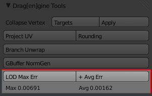
To help artists check the fitness of their LOD meshes the scripts include also a LOD metric calculation based on the LOD metric describe in this page. To use this tool select the base mesh and then the LOD mesh. You can select also two LOD meshes. The meshes are not requied to be linked yet or to be directly next to each other in the LOD chain. Press then the “LOD Max Err” or the “+ Avg Err” button. The maximum and average error is then displayed underneath in meters. A max error of 3-5mm is an optimal value. Smaller than this and the LOD mesh might be skipped often if it is not the last LOD mesh in the chain. A max error up to 0.5-1cm is a good value. With most meshes you will have a max error of 0.5-1cm. For higher LOD meshes the max error should be around 4-5x the max error of the base mesh to the previous LOD mesh. Hence if the max error from LOD-0 to LOD-1 is 4mm then a good max error from LOD-1 to LOD-2 is 1.6-2cm. Of course you can choose different scales if you like. These are values proving good LOD changing steps. The OpenGL Graphic Module allows to visualize LOD levels if you want to get a closer look.
Advanced Usage
An advanced use of the LOD System can be found on the Tree Canopy LOD page.


