Table of Contents
Start Page » Game Development with the Drag[en]gine » Skin Texture Properties » Texture Property Database » normal
Skin Texture Property: normal
Defines the surface normal in tangent space.
| Excepted Data Source | 3 component image |
| Data Range | 0 to 1 for all image components |
| Default Value | (0.5, 0.5, 1) |
| Affected Modules | Graphic, Physics |
| Linked Properties | normal.strength |
Description
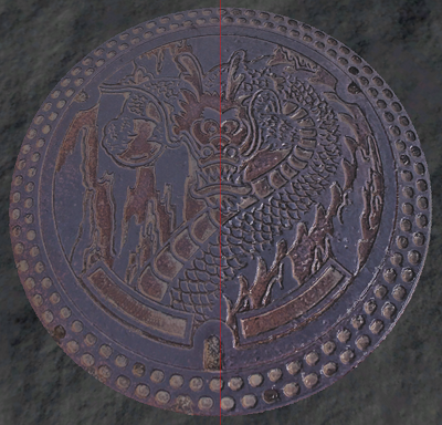
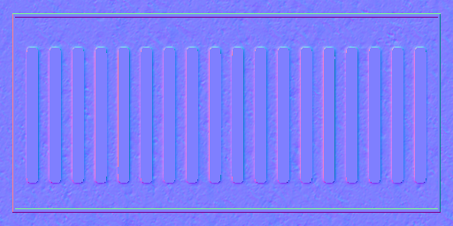
The normal texture property is used to add high resolution light rendering to objects that can not be represented with a low resolution game model. Normal based lighting is a standard in game development since a long time. The basic idea is to use textures to store high resolution surface normals not found on a low resolution model. Such normal map textures are no ordinary color textures. They store normal vectors packed into an 8-bit color. Such a normal map can be produced with various tools but typically two main ways exist.
The color values are typically an 8 bit image with 3 color components with the data of all color components located inside the range from 0 to 1. See the encoding information below.
The default value for this texture property is (0.5, 0.5, 1) or (127, 127, 255) in RGB representing an unaltered normal.
Normals can be modified using other texture properties after reading them from this texture property. If you need faint normal map effects like for example for a slightly uneven window surface you can run into resolution problems with 8-bit images. In this case store the normals excagerated and use the normal.strength texture property to scale down the effect.
History
Normal based lighting is a standard in game development and cinema since a long time. A game without normal mapping tends to look flat because objects lack the dynamic change of light and shadows as we know it from the real world. To deal with this problem some tricks had been created along the years.
It all started with Bump-Mapping. The idea is to encode the change in surface height across a texture mapped on the texture in the red and green channel. The red channel stores the difference in height for a pixel relative to the pixel right next to it. The green channel stores the difference in height for a pixel relative to the pixel right below. Hence the resulting texture can be interprated as a height gradient map for the object. With the gradients a normal can be reconstructed that is then used instead of the real surface normal for lighting calculations. Converting a height difference to a normal like this is not a perfect match and results in problems if the height difference is too large. For adding bumpy details to an object though this technique works well and is still used in production environments nowadays as it is a cheap and fast solution while still delivering good results.
Later on the next step had been the true normal mapping. Here the normal itself is stored in the texture and not the height gradients. This removes conversion and reconstruction calculations resulting in higher quality lighting results. Furthermore with this technique mapping a high resolution mesh to a low resolution mesh became interesting and efficient. Especially organic models suffered under the Bump-Mapping technique since autoring a gradient map is not easy for a complex organic model. Using the normal map though the high resolution model is stored directly resulting in higher quality.
Variations exist in how the normal maps are stored, what components are reconstructed or if even a high definition range image is used to store the normal map. In the end though all these techniques are the same in the end usage. Today normal mapping using these techniques is the defacto standard in game development.
Normal Maps from Images
The quick and often dirty way is to use a normal map plugin for GIMP or other paint applications. These plugins take a color or grayscale image and convert it to a normal map. There exist different operators that can be used to calculate the resulting normal map. They vary in crispness, strength and broadness of pixels covered (in the sense of how much details of neighbors flows into the result). Results obtained with a normal map plugin can vary drastically. There exist tricks to improve the results for example using Photo Normal Reconstruction or using applications specialized in generating normal maps from images. This technique is well suited for Detail Normal Maps hence bumpy surface details of small scale and depth like scratches, leather patterns or embossed text. It is also often used to create normal maps from real world images. For the later though using Photo Normal Reconstruction is recommended but the results vary. For Geometry Normals as required for complex organic models this technique is not well suited at all. Here the second way to create normals maps is better used.
Normal Maps from High Resolution Model
The second way uses a normal map generation too and a set of models. With this technique a high resolution model is used as the source of normal information and mapped onto the texture of a low resolution model. This process is called “Baking” and applications like Blender3D can do this for you as well as external tools specialized on normal map generation using a high polygon model. Using this technique can be tricky as there are various problems that can happen.
One source of problems stems from the fact that ray tracing is required to figure out which surface point on the high resolution model has to be used as the result to store relative to a point on the low resolution model. For this a ray is shot along the low resolution model surface normal for a given point. But what is the right length for this ray? And how far underneath the surface to I have to start to catch cracks and dents in the high resolution model? One solution is to use a cage mesh while other solutions are to split up the model into parts not getting in the way of each other. What you have to do depends on the applications you are using.
Tangent Space Problem
A main problem is the splitting of normals and especially tangents along the low resolution model. The normals have to be transformed relative to a coordinate system located at the point of interest on the low resolution model. This coordinate system is typically called the “Tangent Space” and depends on the normal and tangent vectors at this very point in space. Normals as well as tangents are interpolated in the Drag[en]gine along faces in a low resolution model. Without proper splitting normals and tangents of neighboring faces are averaged resulting in singularities. Even without these singularities normals and tangents can interpolate across the low resolution model in funny ways. Normal map generation tools take care of these peculiarities but there is an annoying problem. These tools usually all work with their own specific definition of a tangent space and how tangents are split across models. These definitions vary only slightly but small differences can have huge visible artifacts as consequences. It is thus crucial to ensure the normal map generation tool produces an output fully consistent with the Drag[en]gine Normal Definition to work properly.
Normal Map Encoding
Another problem is the encoding of normal maps. The components of normals are in the range from -1 to 1 while those of colors are in the range from 0 to 1. The most common solution is to map all normal components directory from -1..1 to 0..1 using one color component for each normal component. For the choice of mapping between the components as well as flipping or not flipping the result there are tons of different ways normals can be mapped. The Drag[en]gine requires the normals to be encoded in the following way to work properly.
| Normal Component | -1 Normal | 0 Normal | 1 Normal | Color Component |
| X | 0 | 127 | 255 | Red |
| Y | 255 | 127 | 0 | Green |
| Z | 0 | 127 | 255 | Blue |
As you can see X maps to red, Y to green and Z to blue. X is the normal component along the tangent direction, Y is the normal component along the bitangent direction and Z is along the surface normal. As a general rule of thumb to check if the image is correct your normal map generator produced you can verify the following properties (switch off colors in your paint application):
| Red Color Only | Image looks like a light source is located on the right side of the image |
| Green Color Only | Image looks like a light source is located on the bottom side of the image |
| All Colors Enabled | Image has a blueish look |
If this holds true chances are good your normal map is usable from the encoding point of view. Make sure your watch the Tangent Space Problem too.
Blender3D GBuffer NormGen Script
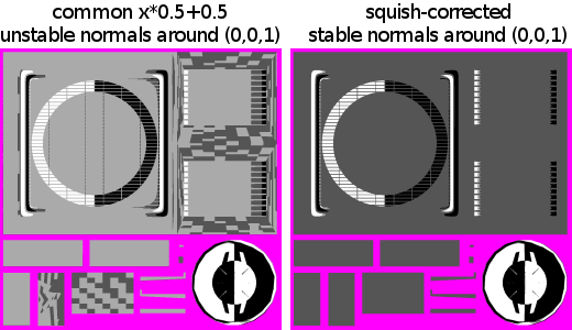
The Blender3D export scripts contain a GBuffer based normal normal generator script. This script converts normals generated by the blender backing process into normals working with the Drag[en]gine. Normal map generators in general have a problem with the middle value. A (0, 0, 1) normal converts to 127.5 . Slight irregularities result in tiny different color values chosen for nearly the same encoded normal. Not visible from the naked eye they turn into artifacts while rendering. Especially texture compression reacts badly to such small irregularities in the normal maps.
The export scripts contain a squish correction to ensure the (0, 0, 1) and similar normals always map properly to (127, 127, 255). The image below shows what to avoid.
Physics Module
The normal texture property can be used for particles to influence their bouncing direction. This aligns the physical response of small particles bouncing off surfaces with the graphical representation of the material.
This kind of in depth simulation is usually not used by pyhsics modules as the effect is subtle and using just the interpolated surface normal is faster.


